Electromagnetic Induction:
If a magnet is pushed into or out of the solenoid, the spindle cuts out the magnet flux. The breaking by the wire coil of the magnetic flux produces a current in the cable. The induced current flows through the circuit while the solenoid is attached to a closed circuit.
Lenz’s law and Faraday’s law will determine the direction of the inductive current and the amplitude of the caused e.m.f by the cutting of the magnetical wave.

Faraday’s Law:
The Faraday Law notes that an e.m.f. is created in the conductor perpendicular to the flux and direction of motion if the flux connects to a carrier. The rate of flux shift is commensurate with the mediated e.m.f. Such are the actual science of the rules. Anyway, what’s flow? Flux is simply the sum of the magnetic field that travels through a single surface.
Lenz’s Law:
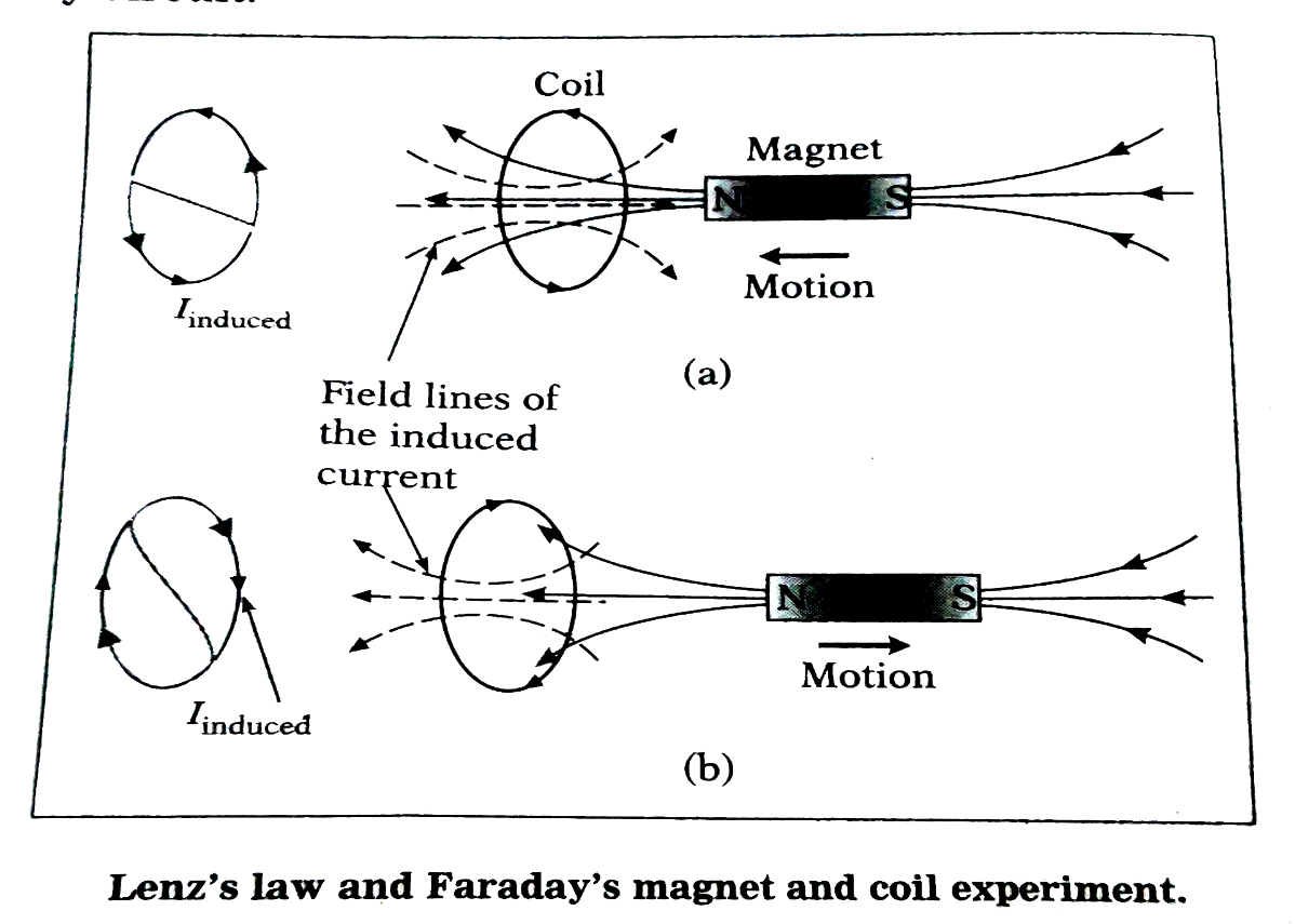
The path of the e.m.f. induced and, thus, the induced current in a closed circuit, is usually such that its magnetic effect is contrary to, or modifies its motion.
This diagram indicates that the galvanometer disconnects as a magnet is pushed into the solenoid, therefore a current flux is necessary. Current existence means that an electrical fiber is created in a circuit that rotates a current through the closed circuit.
There will be no current movement and no defluxion at the galvanometer if the magnet is motionless.
Read also: Sound
A.C. generator:
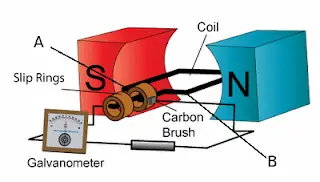
A.C Mechanical energy is transformed into electrical energy by generating electricity. By replacing its commutators with two (separate) rings, the generator can be changed to a.c generator.
Along with the armature (the rectangular coil), the two circles move. Carbon brushes link the frame to the outside connexion. The frame is at the vertical position originally.
There is no decrease in magnetic flow and therefore no induced current.
As the frame rotates, the magnet movement shifts, and the generated current rises to the horizontal limit value. From the Right-Hand law of Fleming, the direction of the mediated current can be calculated. The right-hand rule is used in Fleming in order to determine the direction of the induced current flowing out of the wire whether the magnetic field is sufficiently stable.
As the armature continues on its rotation, the change in magnetic flux decreases until at the vertical position, no induced current exists.
Now upon reaching the horizontal position again, the induced current is maximum, but the direction of the induced current flowing through the external circuit is reversed.
Depending on the angle of the device, the direction of the induced current (which flows through the external circuit). Often known as alternating current, this induced current.
In one way, the current is positive (+) and in the other negative-). Smooth rings play a key role in generating alternative sources.
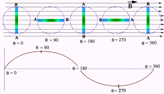
The diagram displays the front view of the frame (A and B seen in the diagram above). This diagram is for one spindle revolution.
The frequency f of the rotation is compared by the equation to its length T:
f > 1 T = 1
We will see from this equation that the doubling of frequency s means that the time T is halved.
The caused e.m.f. of an A.C rise. We will produce
- increase the number of coil spins,
- increase coil rotating frequency
- Using a significantly stronger magnet,
- Use a heart of soft iron.
Transformers:
A transformer is a passive electrical device that passes electronic energy to various circuits from one electric circuit to another.
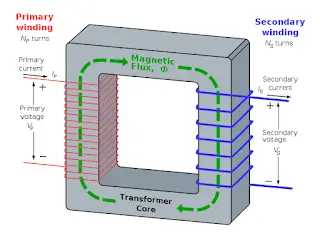
A changing current in each transformer spindle creates a differing magnetic movement in the middle of the transformer, which causes a change in voltage in some other spindle in the same area.
The center and the secondary coil are composed of the main coil.
- The main circuit is the reference energy supply circuit. The main circuit is known as the primary current (ip), the primary potential difference (vp), and the primary belt (primary).
- A main and secondary coil the center of the ferromagnetic metal cut. The key purpose is to move the changeable magnet flux from the primary coil to the secondary spindle.
- The magnetic flux shift as the armature begins to spin until no induced current occurs at the vertical location. The inducted currency now hits the location again as the induced current flows into the external circuit but the path of the induced current flows out.
Now, this is how a transformer works:
- The main wire and a secondary spindle wound is formed on a soft iron foundation.
- A shifting magnetic flow is created around the primary spiral while an alternate flow is in the primary spiral.
- The shifting magnetic current is transmitted through the iron core to the secondary coil.
- A secondary spindle breaks the changeable magnetic flux, thereby causing e.m.f. in the secondary spindle.
- The voltage can be determined according to the combination of primary belt number and secondary belt number.
In a step-up transformer, the e.m.f. of the secondary coil is greater than the e.m.f. of the primary coil. Similarly, in a step-down transformer, the e.m.f. of the secondary coil is less than the e.m.f. of the primary coil. It can be shown that:
Vs / Vp = Ns / Np
where Vs is the secondary output voltage, Vp is the primary input voltage, Ns are the number of turns in the secondary coil and Np are the number of turns in the primary coil.
Ns / Np is called the turns ratio.
Power transfer in a transformer:
Here we’ll consider an ideal transformer that is 100 % efficient, so the power of the primary coil is fully transferred to the secondary coil. Hence, the Principal of Conservation of energy is applied, from where the power in the primary coil = power in the secondary coil.
We know the formula P = VI, right?
So we can say that:
(Ip) (Vp) = (Is) (Vs)
where Ip is current in the primary coil, Is is current in the primary coil, Vp is the primary input voltage and Vs is the secondary output voltage.
Now coming to a non-ideal transformer, there will always be a power loss, i.e. the efficiency is less than 100 %.
Efficiency = (Output power / Input power ) x 100%
Read also: Mass, Weight, & Density
Converting a.c. to d.c.:
We know that the electricity supplied to our homes is in the form of a.c.. But we also know that many appliances require d.c.. So how is a.c. converted into d.c.?
The use of diode is the solution to this! A diode is a semiconductor device that allows a current to flow easily in one direction only. Simple.
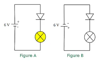
When the diode is connected as in Figure A above, where the anode wire is connected to the positive pole and the cathode connected to the negative pole of battery, we say that forward-biased diode. A diode will only conduct electricity (turn on a light) when given forward bias.
When a diode is connected with reversed polarity as shown in Figure B, where the cathode wire is connected to the positive pole and the anode connected to the negative pole of battery, we say that reverse-biased diode . A diode will not conduct electricity (turn off a light) when given reverse bias.
Half-wave rectification:
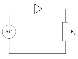
The electrical current is supplied to the circuit is an alternating current generated by a transformer. During the positive half cycle of AC, diodes are forward biased so current can flow. Current that flows through the diode to the load (RL) and back toward the transformer. Then the negative AC half cycle, the diode does not conduct electric current, because given the reverse bias.
Waveform of the current, then, is as shown below:
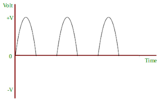
Full-wave Rectification:
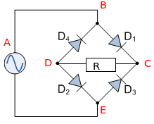
This is the circuit used for full-wave rectification. The four diodes are connected in series. During the positive half cycle of the input voltage, diodes D1 and D2 will conduct, while D3 and D4 will remain off. The current will take the path ABDEF.
Now during the negative half cycle of the input voltage, diodes D1 and D2 will remain off. The current will follow the path FECDBA.
Cathode-Ray Oscilloscope:
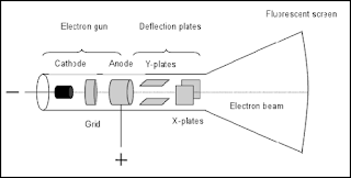
Shown in the diagram is a simple cathode ray oscilloscope.
The device consists mainly of a vacuum tube which contains a cathode , anode , grid , X & Y-plates, and a fluorescent screen.
When the cathode is heated (by applying a small potential difference across its terminals), it emits electrons (this process is called thermionic emission).
Having a potential difference between the cathode and the anode .(electrodes), accelerate the emitted electrons towards the anode, forming an electron beam, which passes to fall on the screen.
When the fast electron beam strikes the fluorescent screen, a bright visible spot is produced. The grid, which is situated between the electrodes, controls the amount of electrons passing through it thereby controlling the intensity of the electron beam.
The X & Y-plates, are responsible for deflecting the electron beam horizontally and vertically.
The front panel of the CRO looks like this:
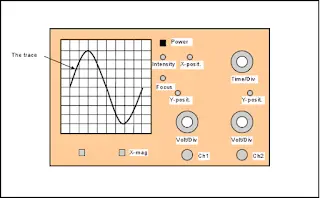
The Y-gain of the CRO amplifies the Y-deflection. Amplifying circuits are built into the CRO so that small input voltages are amplified before they are applied to the Y-plates.
Time-base controls the speed at which the electron beam sweeps across the screen horizontally from left to right.
The settings of the CRO are set, for example time base is set at 0.5 ms/div (0.5 millisecond per division) and the Y-gain is set at 1 V/div (1 volt per division).
And this is how the trace will look like:
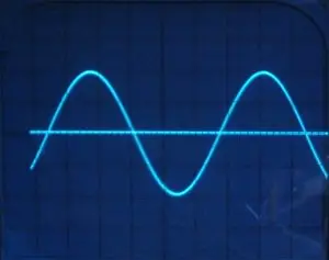
Here you can be asked to find the frequency and the peak voltage.
We know that frequency f is f = 1 / T.
How many divisions across the x-axis is the wave covering? It’s almost five.
So T = 0.5 * 5 = 2.5 ms
For frequency, we need to change it to seconds.
Now for the peak voltage, the wave is covering two divisions, so it will be V = 1 * 2 = 2V.