The one-directional or unidirectional electrical charges are direct current. An electrical cell is an excellent example of DC control.
A conductor such as wiring can flow direct current, but also through seminars, isolators or even vacuums, like electron or ion beams direct current may flow through a vacuum

Series Circuit:
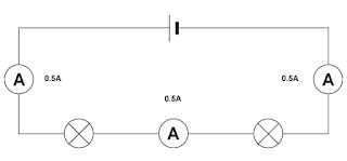
A sequence circuit as seen in the diagram. Both bulbs and meters in series are related. Are you conscious that all meters have the same value? Right, here we are.
circuit the same every time a sequence is running, regardless of how much load you upload. The same current flows in both bulbs above.
Look at the above circuit; it has the same battery and bulb (but only once) and the metre reads the same way. Therefore, load in a series circuit does not influence the current value.
Potential Difference across a series circuit:
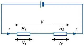
Two resistors are now paired in series in the above diagram. We know that at some point the current will stay the same, only the voltage varies. Only add all voltages on the series circuit to reach the e.m.f., that is:
V (e.m.f. of battery) = V1 + V2
Scientifically, thus, the amount of the possible difference over each element of a series circuit is equal to the potential difference across the whole circuit (e.m.f.).
Read also: Mass, Weight, & Density
Resistance in a series circuit:

Coming to the resistance in a series circuit, consider the same circuit.
Each resistor has R1 and R2 resistance. In current electricity, we discovered formula V = IR. So according to this, p.d. across R1 is V1 is V1 = I R1 and that across R2 is V2 = I R2.
We know that
V = V1 + V2
V = IR1 + IR2
= I (R1 + R2)
Therefore, V / I = R1 + R2.
We can see from the above derivative that the total resistance R is the sum of all the circuit resistors. The combined strength is therefore the sum of all the resistances in a series circuit.
Q1. Determine the current in the ammeters A1 and A2.
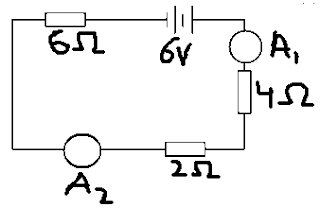
Hint: The current in a series circuit is same and remember how the total resistance is calculated in series.
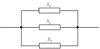
Parallel Circuits:
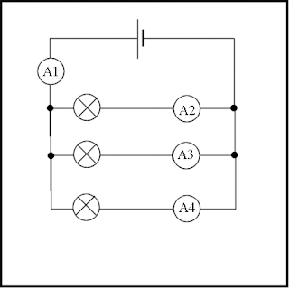
The easy answer would be: there is more than one direction in a parallel circuit where electricity would run. And as we found out that the current around the circuit remains the same in a series circuit. At the same time, its various. Take a look at the circuit below:
From the circuit diagram, you can see that any lamp is branched by itself. The 3 lamps are identical, so the circuit is identical. The junctions are represented by the black dots for each branch.
We notice this when setting up this circuit and connecting meters as shown:
A1 = A2 + A3 + A4
That is, the waves are building up. For all parallel circuits, one important concept is that in each branch the current is equal to the sum.
In more mathematical terminology, in a parallel circuit, each branch is proportional to the principal current in and out of the parallel branch in the sum of the various currents.
P.d. across a parallel circuit:
P.d. in a parallel circuit is more like current in series: it remains the same!
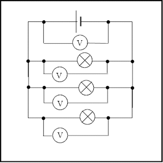
In the circuit above, the p.d. shown on each voltmeter is the same as the battery voltage.
Resistance in a parallel circuit:
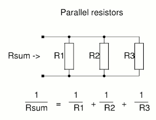
The diagram shows exactly how the combined resistance of resistors in parallel can be found.
Q2. Calculate the total resistance in the following circuit where
R1 = 2 Ω, R2 = 4 Ω and R3 = 6 Ω.
The relation of bulbs in parallel has two advantages. First of all, they shine brighter in parallel as each bulb in series is given a lower voltage than power e.m.f., while all bulbs are fitted with the same e.m.f. More voltage means more power with V = IR because the lamp is luminous! Secondly, as one bulb leaves, the other glows naturally. Parallel to this. When one bulb comes out in sequence, it inevitably breaks and other bulbs will not be lit up.
Read also: Temperature
Differences between series and parallel:
So, below is the difference between both.
- Current remains the same in sequence at all times, with varying voltages. Around the same time, current varies, while voltage at all points is the same.
- Simply add resistors to find maximal resistance in sequence, and apply formula R (absolute) = (1 / R1) + (1 / R2) + (1 / R3) in parallel to this.
- The sum of all p.d.s currently in sequence is e.m.f. Try to recall what we’ve learned P.d. In the energy lesson.
- A new point here is: discovering the P.d. Apply the formula to every load (such as a resistor) where you know the resistance, total circuit resistance and total voltage
P.d. = (R / Rtotal) x Vtotal.
Potential Divider:
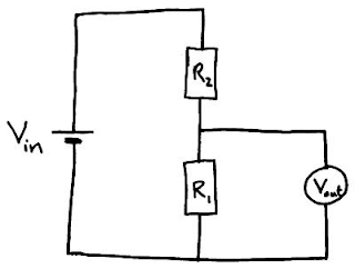
The future divider is not as complex as it seems in its name. It is essentially a series-arranged circuit of resistors. We are familiar with the potential difference between individual resistors in a series setting depending on the resistance of the resistor.
Take a look at a simple potential divider circuit above. Vin is the e.m.f. supplied by the cell which has been divided into two potential differences across each resistor R1 and R2. The Vout across R1 is then used to drive another part of circuit.
We can find the current through the resistors R1 and R2 by using:
I = (V / R1 + R2)
Hence the potential difference Vout across R2 is given by:
Vout = IR2 = (V / R1 + R2) x R1
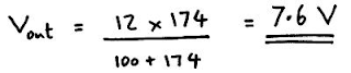
Now find the Vout in the following diagram:
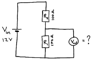
Here’s how you’ll solve it: