When you learn electronics, logical gates are an essential term. These are big computing instruments focused predominantly on the Boolean function.
Single or several binary inputs and a single binary output are equipped with logical gates. The conceptual doors in a computer system are, literally, electrical devices.

In this class, with your truth table we will look at the various kinds of simple logical gates and learn what each is intended for.
Types of Basic Logic Gates
There are several basic logic gates used in performing operations in digital systems. The common ones are;
- OR Gate
- AND Gate
- NOT Gate
- XOR Gate
Additionally, these gates can also be found in a combination of one or two. Therefore, we get other gates such as NAND Gate, NOR Gate, EXOR Gate, EXNOR Gate.
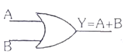
OR Gate
In OR gate the output of an OR gate attains the state 1 if one or more inputs attain the state 1.
The Boolean expression of OR gate is Y = A + B, read as Y equals A ‘OR’ B.
The truth table of a two-input OR basic gate is given as;
| A | B | Y |
| 0 | 0 | 0 |
| 0 | 1 | 1 |
| 1 | 0 | 1 |
| 1 | 1 | 1 |
Read also: Magnetism
AND Gate
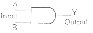
In AND gate the output of an AND gate attains the state 1 if and only if all the inputs are in state 1.
The Boolean expression of AND gate is Y = A.B
The truth table of a two-input AND basic gate is given as;
| A | B | Y |
| 0 | 0 | 0 |
| 0 | 1 | 0 |
| 1 | 0 | 0 |
| 1 | 1 | 1 |
NOT Gate
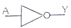
In NOT gate the output of a NOT gate attains the state 1 if and only if the input does not attain the state 1.
The Boolean expression is Y = \bar{A}Aˉ, read as Y equals NOT A.
The truth table of NOT gate is as follows;
| A | Y |
| 0 | 1 |
| 1 | 0 |
The three gates (OR, AND and NOT), when connected in various combinations, give us basic logic gates such as NAND, NOR gates, which are the universal building blocks of digital circuits.
NAND Gate
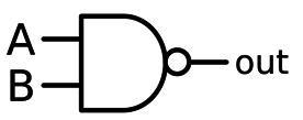
This basic logic gate is the combination of AND and NOT gate.
The Boolean expression of NAND gate is Y = \bar{A.B}A.Bˉ
The truth table of a NAND gate is given as;
| A | B | Y |
| 0 | 0 | 1 |
| 0 | 1 | 1 |
| 1 | 0 | 1 |
| 1 | 1 | 0 |
NOR Gate
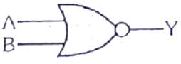
This gate is the combination of OR and NOT gate.
The Boolean expression of NOR gate is Y = \bar{A+B} A+Bˉ
The truth table of a NOR gate is as follows;
| A | B | Y |
| 0 | 0 | 1 |
| 0 | 1 | 0 |
| 1 | 0 | 0 |
| 1 | 1 | 0 |
Exclusive-OR gate (XOR Gate)
In the XOR gate the output of a two-input XOR gate attains the state 1 if one adds only input attains the state 1.
The Boolean expression of the XOR gate is \bar {AB} + \bar {AB}\, or\, Y = A \bigoplus BABˉ+ABˉorY=A⨁B
The truth table of an XOR gate is;
| A | B | Y |
| 0 | 0 | 0 |
| 0 | 1 | 1 |
| 1 | 0 | 1 |
| 1 | 1 | 0 |
Exclusive-NOR Gate (XNOR Gate)
In the XNOR gate the output is in state 1 when its both inputs are the same that is, both 0 or both 1.
The Boolean expression of XNOR gate Y = A.B +\bar{AB} + \bar{AB}\, or\,
Y = \vec{A\bigoplus B}Y=A.B+ABˉ+ABˉorY=A⨁B
The truth table of an XNOR gate is given below;
| A | B | Y |
| 0 | 0 | 1 |
| 0 | 1 | 0 |
| 1 | 0 | 0 |
| 1 | 1 | 1 |
Application of Logic Gates
There are several applications of logical gates, but they are focused primarily on how they work or the truth table.
Basic logic gates are commonly used on circuits such as a safety thermostat, a push-button switch, the integrated watering system and light-triggered burglar warning systems.
The key advantage is that a mixture of various configurations will use simple logic ports, if the operations are advanced. In addition, the number of doors to be used with a single system is not capped.
However, the physical space in the system may be constrained. An array of the logical gate area device is used in digital integrated circuits (ICs).
De Morgan’s Theorem
First theorem – It states that the NAND gate is equivalent to a bubbled OR gate.
\bar {A. B} = \bar{A}+ \bar{B}A. Bˉ=Aˉ+Bˉ
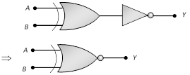
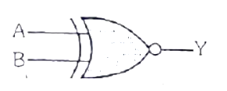
Second theorem – It states that the NOR gate is equivalent to a bubbled AND gate.
\overline{A+B} = \bar{A}. \bar{B}A+B=Aˉ.Bˉ
Important Conversions
Read also: Practical Electricity
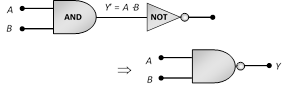
The ‘NAND’ gate:
From ‘AND’ and ‘NOT’ gate.
Boolean expression and truth table:
Y=A⋅B
| A | B | Y′=A⋅B | Y |
| 0 | 0 | 0 | 1 |
| 0 | 1 | 0 | 1 |
| 1 | 0 | 0 | 1 |
| 1 | 1 | 1 | 0 |
The ‘NOR’ gate:
From ‘OR’ and ‘NOT’ gate
Boolean expression and truth table:
Y=A+B
| A | B | Y′=A+B | Y |
| 0 | 0 | 0 | 1 |
| 0 | 1 | 1 | 0 |
| 1 | 0 | 1 | 0 |
| 1 | 1 | 1 | 0 |
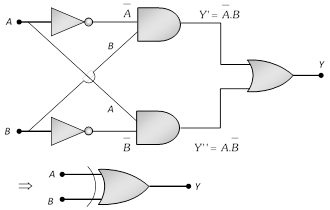
The ‘XOR’ gate:
From ‘NOT’, ‘AND’ and ‘OR’ gate.
The logic gate which gives a high output (i.e., 1) if either input A or input B but not both are high (i.e. 1) is called exclusive OR gate or the XOR gate.
It may be noted that if both the inputs of the XOR gate are high, then the output is low (i.e., 0).
Boolean expression and truth table: Y=A⊕B=A¯B+AB¯¯¯¯
| A | B | Y |
| 0 | 0 | 0 |
| 0 | 1 | 1 |
| 1 | 0 | 1 |
| 1 | 1 | 0 |
The Exclusive nor (XNOR) gate XOR + NOT
Boolean expression: Y=A⊙=A¯B¯+AB