Electric Current:
An electrical current is a circuit power load surge. In fact, the electrical flow rate is the flow rate over a given point in an electrical circuit. The charge may be electrons with negative charges or positive charges of protons, weak ions or holes.

Electric current (I) is an electrical charge (Q) flux rate measurement through a given cross section of a conductor.
This is how:
I = Q / t
Ampere (A) is the SI unit. For the measurement of current, an ammeter is used.
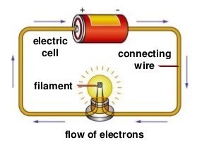
You should all know how a simple circuit looks now before moving forward.
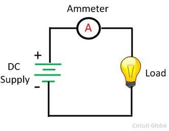
In the circuit shown above, it consists of:
- a source of electromotive force that drives electric current (e.g. battery)
- a load on which moving charges can do a useful job (e.g. a bulb)
- conductors to connect the components together (e.g. copper wire)
- switch to open or close a circuit.
Electromotive Force and Potential Difference:
The energy needed to move the positive charge of the unit from one end of the circuit to another is electromotive force (i.e.m.f). This is how:
E = W / Q W / Q
Where E is the electricity e.m.f. supply, W is the amount of electric power converted from electrical to non-electric forms (work done). The e.m.f. SI unit is Joule per volt (V).
Recall that e.m.f. has load movement across the whole circuit.
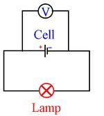
This last diagram indicates the measured voltage of the cell and thus e.m.f., as the cell supplies voltage to the full circuit.
Possible variation is also the amount of electric energy required to transfer positive unit charges in the electrical system from one level to another. This is how:
V= W / Q V = W
Where V is p.d., W is the transferred electrical energy in certain ways and that Q is the charge volume. Of this the SI unit is equivalent to e.m.f. and volt (V).
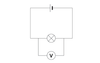
The diagram shows how p.d. can be calculated across the bulb (between two points).
Read also: Temperature
Resistance:
Resistance, as the name suggests, is the measure of how difficult it is for an electric current to pass through a material, copper wire let’s say. So it is basically the restriction (resistance) of a material to the free moving electrons in the material. If you compare it with the friction in moving objects, it’s quite correct.
Now in more scientific terms, resistance R of a component is the ratio of the potential difference across it to the current I flowing through it, such that:
R = V / I
where R is resistance, V is the p.d. across the component (note that across a component, that is, between two points, it’s p.d. and not e.m.f.) and I is the current flowing through it.
The SI unit of resistance is the ohm (Ω).
Resistance is measured using a conductor called a resistor. Resistors are of two types: fixed and variable (rheostats). Now you can tell exactly from the name what these are, right? Fixed resistors have a fixed value while variable resistors can vary the resistance and are used in circuits to vary current.
Ohm’s Law:
Ohm’s Law states that the current passing through a metallic conductor is directly proportional to the p.d. across the ends, provided the physical conditions (such as temperature) are constant.
Such that:
I α V
where I is current and V is p.d.
and this drives us to the formula which we have already learned, i.e.
V / I = constant = R
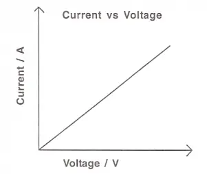
From this, we can make another conclusion that the resistance of a metallic conductor remains constant under steady physical conditions, and such conductors that obey Ohm’s law are called ohmic conductors. For ohmic conductors, I-V graph has a constant gradient (i.e. the inverse of resistance), as shown below:
Not all conductors obey Ohm’s Law, such conductors are non-ohmic conductors. The resistance of such conductors can vary, but how do we differentiate? The I-V graphs of different conductors can help us differentiate.
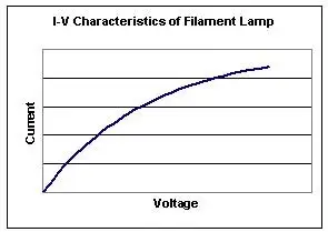
For example, for a filament lamp, when the p.d. across the lamp increases, the current does not increase proportionally. The graph below makes it clearer:
The deviation of the I-V graph from the straight line is due to an increase in the resistance of the filament with temperature.
The graph is a straight line in the initial stage because the increase in resistance of the filament with the temperature due to small current is not appreciable.
As the current is further increased, the resistance of the filament continues to increase due to rise in temperature (Though the gradient is decreasing, how can we say that the resistance is increasing? That’s because the slope is the inverse of a gradient in this case).
How is the temperature rising? It’s rising because as the bulb remains on for a long time, more energy is dissipated to heat energy.
Task: Google other non-ohmic conductors and find out how their resistance varies in an I-V graph.
Read also: Static Electricity
Resistivity:
Apart from temperature, there are other factors as well on which R depends. As for temperature, the higher the temperature of metallic wire, the larger the resistance.
The resistance depends on
- the length l of the wire,
- the cross-sectional area A or thickness of the wire, and
- the type of material.
To memorize how these factors affect the resistivity of the conductor, memorize the following formula:
R = p (l / A)
where R is the resistance, p (a constant) is the resistivity, l is the length and A is the cross-sectional area of the wire.
This shows that R α l and that R α 1 / A.
So now I have made it quite easy: as R is directly proportional to length, the longer the length of the wire, the greater is its resistance, and as R is inversely proportional to the cross-sectional area of the wire, the greater is its cross-sectional area, the lower is its resistance.
Now for the type of material, every material has a different resistance. For example, the resistance of silver is 1.6 x 10⁻⁸ Ω while that of graphite is 3000 x 10-8 Ω.